
| Donate $25 for two DVDs of the Cryptome collection of files from June 1996 to the present |
30 December 2000
Source: Hardcopy from the National Security Agency in response to an appeal of an earlier FOIA request for TEMPEST-related documents. This is one of three full and five partial documents received under the appeal. See NSA letter and list of documents: http://cryptome.org/nsa-foia-app2.htm
For comprehensive TEMPEST information see: http://eskimo.com/~joelm/tempest.html
[9 pages; all marked: FOR OFFICIAL USE ONLY]
SPECIFICATION NSA NO. 94-106
SPECIFICATION NSA NO. 94-106
date: 24 October 1994
SUPERSEDING
SPECIFICATION NSA NO. 65-6
30 October 1964
NATIONAL SECURITY AGENCY
SPECIFICATION FOR
SHIELDED ENCLOSURES
1. SCOPE. This specification provides the general requirements for the installation and performance of shielded enclosures to attenuate electromagnetic radiation. This specification shall be reviewed at least every three years. The requirements of this specification apply to all associated and auxiliary facilities furnished as part of a shielded enclosure.
2. APPLICABLE DOCUMENTS. The following document in effect on the date of invitation forbid forms apart of this specification to the extent specified herein:
Military MIL-STD-220A Method of Insertion-Loss Measurement
3. REQUIREMENTS
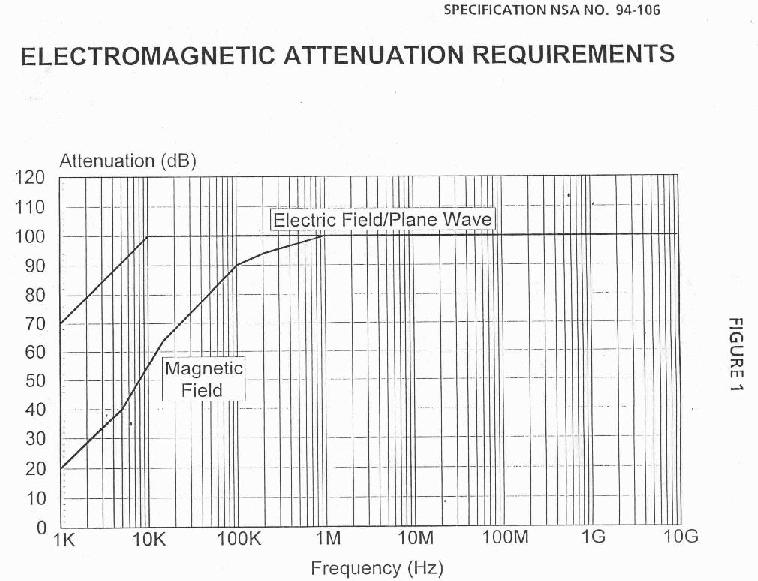
3.1 Performance. The shielded enclosure shall meet the requirements for electromagnetic attenuation as specified in Figure 1.
3.2 Design. Maximizing electromagnetic attenuation shall be stressed throughout the shielded enclosure's design, construction and erection. Where demountable construction is required, the enclosure shall be constructed to allow for easy disassembly and reassembly with a minimum of effort and without degrading attenuation.
3.3 Reliability. The shielded enclosure will be subject to varying floor loads, repeated use of access doors, and continuous use of the HVAC and electrical filters. When maintained in accordance with the manufacturers preventative and routine maintenance instruction, it shall retain the specified attenuation for a minimum of five years without retightening of bolts (if used), seams or other major maintenance.
3.4 Material. All materials, parts, mechanical and electrical assemblies shall be new, unused, undamaged, of quality consistent with the proposed use and specified performance, and in accordance with referenced documents. All material shall be free from defects and imperfections that might affect the serviceability and appearance of the finished product.
3.5 Warranty. The contractor shall stipulate in writing that the shielded enclosure furnished under the requirements of this specification will meet and maintain the appropriate attenuation requirements f or not less than five years after initial installation. The contractor shall be responsible for the repair or replacement of any part which reduces the attenuation below the required level.
3.6 Publications and Drawings. A minimum of two sets of publications, instructions and drawings for the enclosure shall be provided in a bound, durable binder detailing at least the following:
a. Assembly and disassembly of the shielded enclosure including individual diagrams of each stage of assembly and disassembly, showing framing, enclosure panels and all internal finishing materials and accessories.b. Assembly and installation of the HVAC system, ducts and all penetrations. (see 6.1 (e)).
c. Electrical wiring, including electrical panel layout (if required), installation and wiring of electrical filters, isolators, and grounding.
d. Preventive and routine maintenance including instructions, schedules, and appropriate replacement parts list by item identification and part number.
e. Load limits for all surfaces of the shielded enclosure.
f. Each ancillary device furnished under the contract.
Detail shall include a bill of materials that clearly indicates and identifies all component parts by manufacturer's name, part number, and description.
3.7 Enclosure Structure
3.7.1 Size. The dimensions of the enclosure will be as specified in the contract.3.7.2 Shielding Material. The selection of shielding material will be at the option of the contractor unless specified in the contract. It must be noncorrosive material. Contact between dissimilar metals that causes corrosion must be avoided.
3.7.3 Joints/Seams. If bolted construction is used, then seams must be bolted from the inside only. Joints of double-walled enclosures may have outside bolted joints on outside walls, provided there is sufficient space in the parent room adjacent to the walls to allow retightening of the outside bolts.
3.7.4 Special Tools. The contractor shall supply any tools required to install the enclosure.
3.7.5 Workmanship. The enclosure and accessories shall be free from defects that may affect appearance or serviceability and shall conform to the requirements of this specification.
3.7.6 Surface Requirement. Wall, floor and ceiling covering shall be as specified in the contract. A suitable system to support cables, pipes, special fixtures, etc. around the inner or outer surfaces of the enclosure shall be as specified in the contract. The floor and floor covering shall be capable of withstanding the floor loading requirements specified in the contract. Attenuation characteristics shall not be adversely affected by noncorrosive liquids-accumulating on top the enclosure, or from noncorrosive spills within the enclosure, or from the presence of water or moisture on the parent room floor.
3.8 Additional Requirements.
3.8.1 Access Doors. Door hinges shall support the door's weight without sagging. Doors shall have closing and latching mechanisms to provide positive closure, so that the entire door area including juncture between door and frame at all points meets the attenuation requirements.3.8.2 HVAC. HVAC ducts shall not restrict the flow of air required for proper operation of the air conditioner. It is the contractor's responsibility to ensure that HVAC installation does not degrade the attenuation of the enclosure.
3.8.3 Power and Line Isolation. Isolation devices shall be provided for each *line penetrating the shielded enclosure. The devices are to be mounted so as not to degrade the enclosure's attenuation. The power isolation system shall provide a minimum of 100 dB insertion loss from 1 KHz to 10 GHz.
3.8.4 Grounding. A single ground lug connected to the shield surface shall be provided. This lug shall be connected to the nearest building structural member. This connection shall have DC resistance of 1 ohm or less with the ground connection in place, and 10 megaohms or greater with the ground connection removed.
4. QUALITY ASSURANCE PROVISIONS
4.1 Contractor's Responsibility. Unless otherwise specified herein, the contractor is responsible for the performance of all inspection requirements prior to submission for contracting officer's representative inspection and acceptance. Except as otherwise specified, the contractor may utilize his own facilities or any commercial laboratory acceptable to the Government. Inspection records for examinations and tests shall be complete and available to the Government. The Government reserves the right to perform any of the inspections set forth in this specification, where such inspections are deemed necessary to assure supplies and services conf orm to prescribed requirements.
4.2 Inspections and Tests.
4.2.1 In Process Inspections. During construction, the contracting officer's representative reserves the right to conduct recurrent inspections at the contractor's plant. It shall be the responsibility of the contractor to extend full cooperation to the contracting officer's representative during such inspections, and to advise the representative of any deviations from applicable specifications.4.2.2 Acceptance Inspection. Acceptance inspection shall be conducted under the supervision of a contracting officer's representative. All necessary personnel, facilities and test equipmentfor performing tests and inspection required by this specification shall be furnished by the contractor. Test equipment shall possess the necessary calibration, frequency range, sensitivity, power output, accuracy and quality for the required tests.
4.2.2.1 Contractor Installation. The contractor shall perform the acceptance tests of paragraph 4.3 at the site of installation.4.2.2.2 Other Installations. On contracts not requiring on-site erection, the contractor shall perform the acceptance tests of paragraph 4.3 at its plant on a sample shielded enclosure that is similar to the enclosure(s) to be delivered in all characteristics which affect attenuation properties.
4.3 Acceptance Tests. Acceptance tests shall be performed in accordance with the procedures detailed in this section for electromagnetic attenuation. A test plan, detailing test locations, shall be submitted and approved prior to performance of the tests.
4.3.1 Electromagnetic Attenuation Tests. (Figure 1)4.3.1.1 Equipment.Continuous wave (CW) source, 1 KHz to 10 GHz.Transmitting and receiving magnetic field antenna set covering 1 KHz to 1 MHz.
Transmitting and receiving electric field and plane wave antenna set covering 1 KHz to 10 GHz.
Receivers or spectrum analyzers covering 1 KHz to 10 GHz with adequate dynamic range to measure the attenuation required in Figure 1.
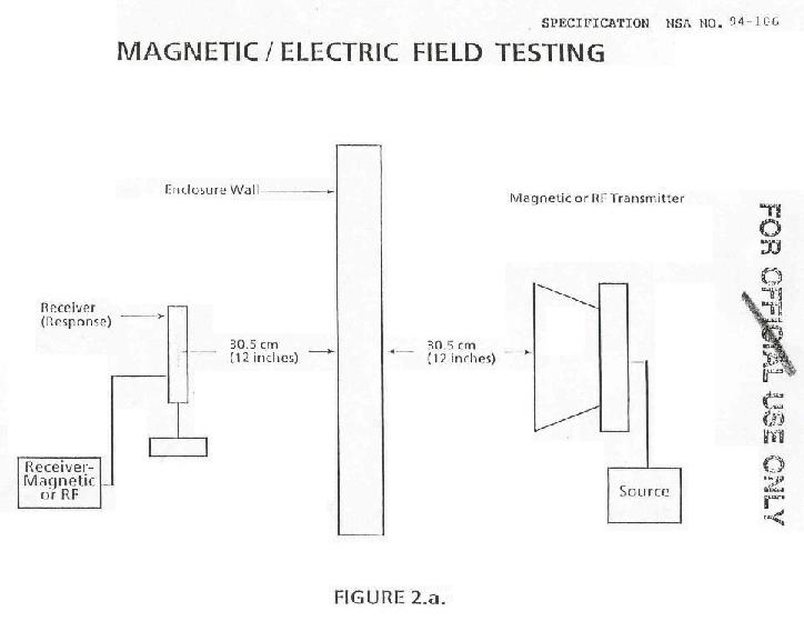
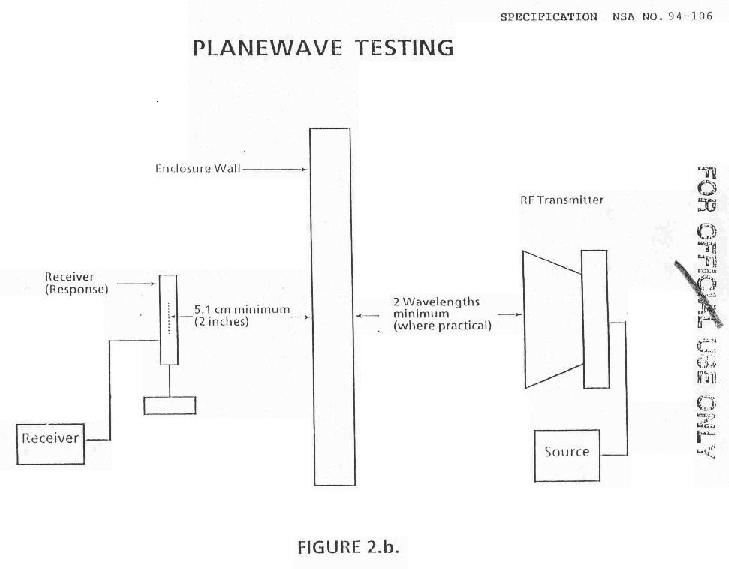
4.3.1.2 Magnetic/Electric/Plane Wave Test. The magnetic and electric f ield attenuation tests shall be performed with the antennas located directly opposite each other and separated by a distance of 61 centimeters (24 inches) plus the wall thickness (See Figure 2.a.) Magnetic field attenuation shall be measured at 1 kHz, 10 kHz, 100 kHz, and 1 MHz. Electric field attenuation shall be measured at 1 kHz, 10 kHz, 100 kHz, 1 Mhz, and 10 MHz. The plane wave attenuation test shall be performed with the transmitting antenna placed at least 6 meters away from the enclosure surface (where practical) and the receiving antenna set no closer than 5.1 centimeters (2 inches) from the wall (See Figure 2.b.) Plane wave attenuation shall be measured at 100 MHz, 400 MHz, 1 GHz, and 10 GHz. Measurements, for all tests, shall be taken with the antennas oriented for maximum received signal strength. Attenuation tests shall be performed around the entire door frame, air ducts, filters and through any accessible joint or penetration. In addition, the magnitude and location of the maximum signal level emanating from the enclosure shall be determined by testing at least f our locations. The selection of testing locations should include not only walls, but also the floor and ceiling. Tests shall be performed, at a minimum, on every 180 square feet of surfade area. All test locations and results shall be documented. The lowest attenuation level performed from all the tests shall be recorded as the attenuation of the enclosure. If possible, all tests should be performed with the receiver outside and the transmitter inside the enclosure. The Government reserves the right to require tests at specific frequencies and locations to determine compliance of the enclosure with this specification.
4.3.2 Filter Insertion Loss. All installed isolation devices shall be tested for their insertion loss or attenuation. Power filters shall be tested for insertion loss in accordance with MIL-STD-220A. All filters shall be installed on the enclosure for the attenuation tests. All power filters shall also be tested for voltage drop (not to exceed 2%) under one half and full rated current. They must operate under full load for ten hours before testing. The increase in temperature of the case during this period must not exceed 25o Centigrade (77o Fahrenheit) above the ambient temperature of the room.
5. PREPARATION FOR DELIVERY
5.1 Preservation, Packaging and Packing. All enclosure hardware shall be packaged in a secure manner, sealed appropriately and shipped using approved security measures to prevent tampering.
5.2 Packing List. A complete packing list shall be provided, showing exactly where every part of the enclosure is packed. This applies to room size enclosures vice whole structure shielding. The packing list when applicable shall include the crate number for each part and its location within the crate.
6. NOTES
6.1 OrderingData. Procurement documents shall specify the following:
a. Title, number and date of this specification and any amendment thereto.b. Whether the enclosure(s) shall be installed by the contractor, or whether the contractor shall perform acceptance tests on a sample enclosure.
c. Area dimensions of the parent room and available electric power at the installation site.
d. Environmental conditions of the parent room and heat dissipation load (equipment, lights and personnel) within the enclosure(s).
e. Whether the contractor shall furnish an air conditioning unit; if so, specify temperature and humidity requirements.
f. Size(s) of enclosure(s).
g. Number, size, location and opening direction of access door(s).
h. Type of floor, floor covering and floor loading requirements.
i. Type of wall and ceiling covering.
j. Size and location of service entrance panels complete with arrangement drawing of connectors.
k. Type, size and quantity of signal and power line c6nnectors for service entrance panel(s).
l. Quantity, voltage and current requirements of power line filters; requirements for signal line filters (or isolators), including: type, frequency, insertion loss, voltages, currents, power, impedance, mounting requirements, etc.
m. Lighting and convenience receptacle requirements.
n. Grounding facilities characteristics.
o. Preparation for delivery.
p. Exception to inside bolted joint if applicable.
q. Security clearance of construction and test personnel.
r. Whether the contractor shall furnish combination lock(s) for access cloor(s), and the approved type, when appropriate.
6.2 Disclosure of Information. The contractor shall not divulge any information as to the requirements of this specification to any person not specifically authorized in writing to receive such information by the:
Maryland Procurement Office
Attn: N1
9800 Savage Road
Ft. George G. Meade, MD 20755-6000
6.3 When requesting copies, stipulate the title, number of the specification and the purpose for which required.
6.4 Changes/Clarifications. Recommended corrections, additions, deletions or clarifications to this specification should be addressed to:
Maryland Procurement Office
Attn: C9
9800 Savage Road
Ft. George G. Meade, MD 20755-6000
NOTICE: When Government drawings, manuals, specifications or other data are used for any purpose other than in connection with a Government procurement operation, the United States Government thereby incurs no responsibility or any obligation whatsoever. The fact that the Government may have formulated, furnished, or in any way supplied the said drawings, specifications, or other data is not to be regarded by implication or otherwise as in any manner licensing the holder or any other person or corporation, or conveying any rights or permission to manufacture, use or sell any patented invention that may in any way be related thereto.
Transcription and HTML by Cryptome.
NSA also provided another document entitled "Specification NSA No. 89-02, TBD, National Security Agency Specification for Shielded Enclosures." [No date]. It is marked: "Superceding Specification NSA No. 65-6, 30 October 1964," and "Specification NSA No. 73-2A, 15 November 1972." The text is almost identical to the document above which appears to have superceded it, thus it has not been transcribed.